Rendering Points as Spheres With Displacement in Houdini
Here is a step-by-step guide to rendering points as spheres in Houdini with a displacement shader.
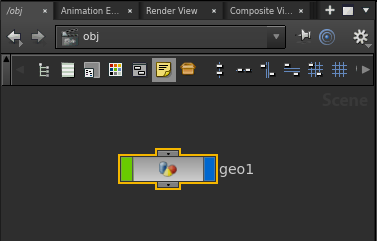
First of all, start up a new scene in Houdini, and in the /obj/ context,
lay down a new Geometry object:
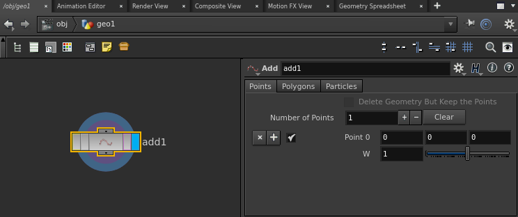
Now, dive into this node and place down an Add SOP. Set ‘Number of Points’ to 1, and enable the first point. We will leave its’ position at the origin.
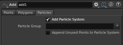
Whilst still on the Add SOP, switch to the ‘Particles’ tab and enable ‘Add Particle System’. This will add a particle system primitive to the stream. It seems that whilst particles can have displacement shaders applied, plain points cannot.
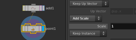
Next, we are going to give our point a radius. Feed the result of the Add SOP into a Point SOP, and on its’ ‘Particle’ tab, switch ‘Keep Scale’ to ‘Add Scale’, and set the scale value to ‘1’.
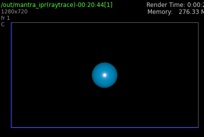
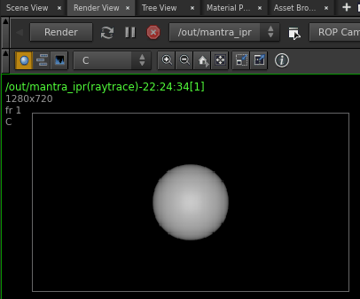
At this stage, we should be able to set up a simple Mantra render and verify that our point is rendering as a unit sphere.
To do this, switch to the /out/ context and lay down a mantra ROP. Switch
to the ‘Render’ panel and hit ‘Render’. You should see a default-lit unit-sphere
in the resultant image.
We are now going to set up a displacement shader. In the /SHOP/ context,
lay down a Material Shader Builder node, and dive inside of it.
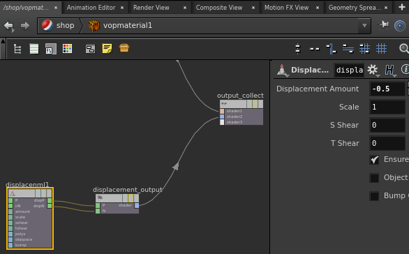
By default, this network should already have an empty surface and displacement shader. Lay down a Displace Along Normal VOP, and connect its ‘dispP’ and ‘dispN’ outputs to the ‘P’ and ‘N’ inputs on the ‘displacement_output’ node. In the ‘Parameters’ panel, set the ‘amount’ to -0.5.
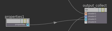
We also need to supply Mantra with displacement bounds (if you don’t, you will probably observe dicing artefacts). We can do this by laying down a Properties VOP in our material, and connect its’ output to the third input on the ‘output_connect’ node.
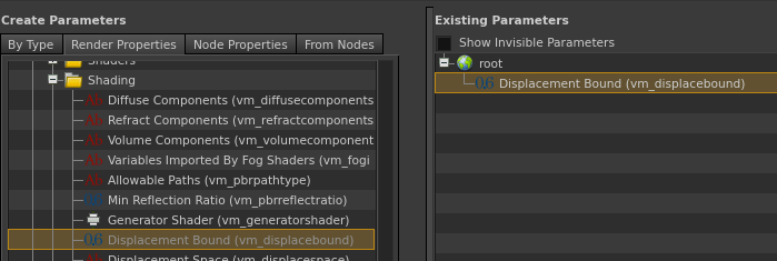
Once you have done this, right-click the Properties node and select ‘Edit Parameter Interface…’. In the dialog that appears, find the ‘Render Properties’ tab, and inside this, drag the ‘Mantra -> Shading -> Displacement Bound’ parameter into the middle panel underneath ‘root’ and hit ‘Accept’.
Now we can select the Properties node, and in the ‘Parameters’ panel, set the ‘Displacement Bound’ parameter to 0.5, to match the magnitude of our displacement value.
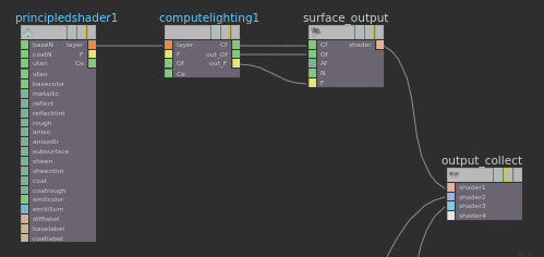
At this point, we should also add a surface shader so that the material renders properly. This can be easily done by placing a ‘Principled Shader’ VOP, which should automatically place a ‘Compute Lighting’ VOP and connect itself to the surface output, as shown below:
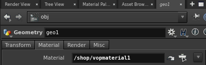
The final thing we need to do is assign our new material to our points. To do this,
go back to the /obj/ context and select the geometry object. In the ‘Parameters’
panel, find the ‘Material’ tab, and underneath this, set the ‘Material’ path to point
to your new material VOP.
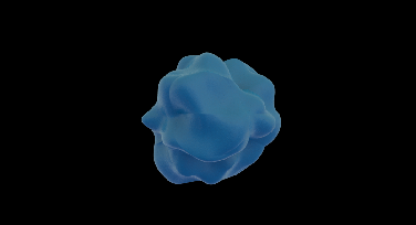
Now we can head back to the ‘Render’ panel and hit ‘Render’ again. This time, the sphere should appear half-as-large, and this is a result of the negative displacement along the surface normal.